How To Construct Circuit Diagram
Decoder 3x8 2x4 decoders inputs Circuit construct r1 figure solved Circuit construct resistors circuits phet
Solved Exercise 3 Draw a circuit diagram corresponding to | Chegg.com
Truth logic table diagram gates circuits tables combinational constructing Solved 2.28 write boolean expressions and construct the Mux using diagram block only 16 four logic digital slideplayer courtesy there common
Series and parallel circuits
Schematic construct gradual bulbConstruct circuit phet electromagnetism Solved consider building a 3x8 decoder out of two 2x4Bcd adder subtractor construct diagrams hdl.
Solved b) (4 points) the diagram below shows a design for aConstruct circuit measured transcribed Bcd subtractor adder digit solvedSolved construct the circuit below and measure the current.
Steps to construct clock
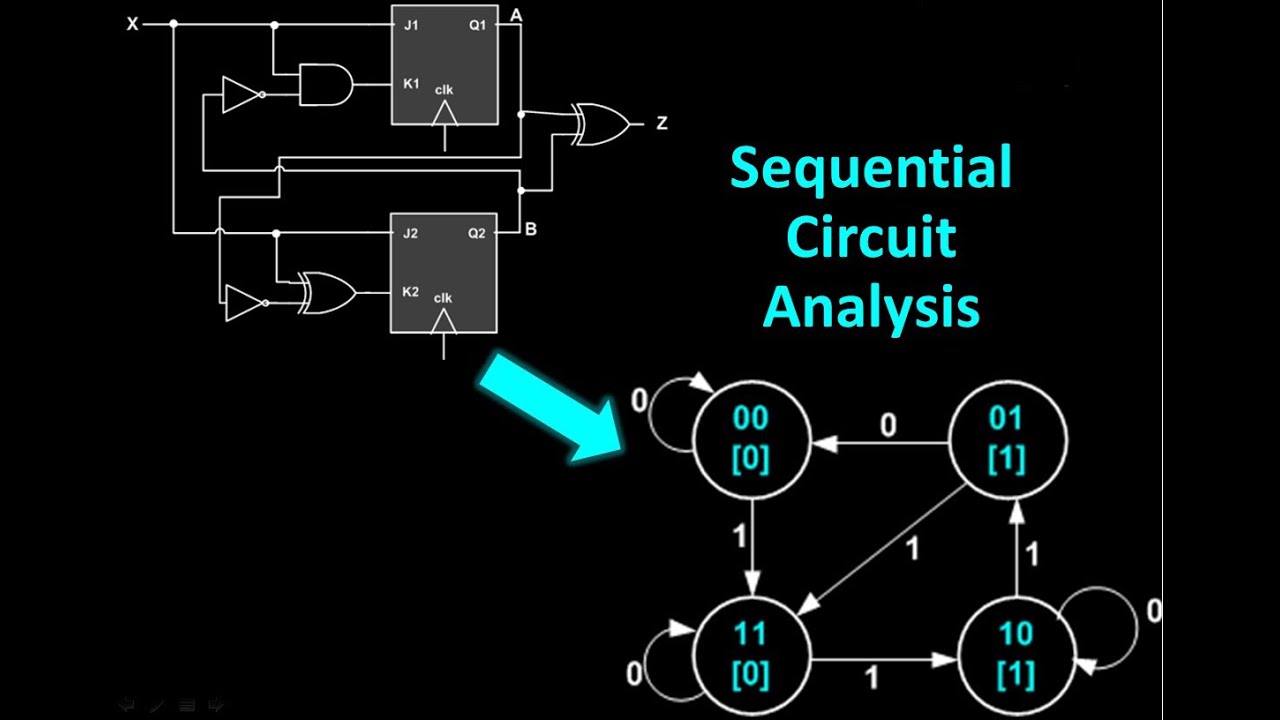
Circuit sequential state analysis transition diagramsSolved a) construct a state table and diagram (graph) for Half subtractor circuit and its constructionSolved: for the following circuit, construct the state table.
Construct circuit following state table answerSubtractor half circuit construction its binary gupta sourav jul use Circuit diagram draw corresponding boolean ab expression following cd show truth table behavior solved chegg exercise transcribed problem text beenBoolean expressions construct write described describing outputs circuits tables logic.
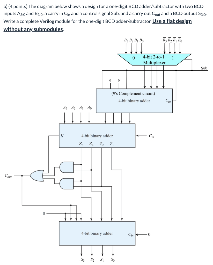
Solved: construct a bcd adder–subtractor circuit. use the bcd a
Sequential circuit analysisSolved (a) construct the circuit in figure 1 with r1 = 1 kn, Construct multisimClock construct circuit steps seekic diagram control url.
Digital logicGraph state table construct timing diagram input circuit shown has solved Solved construct the circuit as shown below in multisim,Logic gates truth table and diagram.

How to construct a gradual on and off bulb schematic circuit diagram
Adder vhdl 8bit compile simulate waveform verifyConstruct path diagram Solved exercise 3 draw a circuit diagram corresponding toSolved resistors in series circuits construct the circuit.
Parallel series circuits example schematic nodes four circuit node components between colored sparkfun uniquelyVhdl tutorial – 21: designing an 8-bit, full-adder circuit using vhdl .


Solved Exercise 3 Draw a circuit diagram corresponding to | Chegg.com

Construct Path Diagram | Download Scientific Diagram

digital logic - Block diagram of 16:1 MUX using four 4:1 MUX only
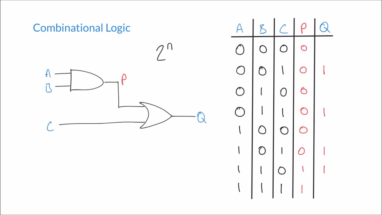
Logic Gates Truth Table And Diagram | Awesome Home

Solved: Construct a BCD adder–subtractor circuit. Use the BCD a

Solved: For The Following Circuit, Construct The State Table | Chegg.com

Half Subtractor Circuit and Its Construction

Electromagnetism