Igbt Inverter Circuit Diagram Pdf
Transformerless inverter circuit diagram pdf Inverter mosfet circuits diagrams Designing 1kw sine wave inverter circuit
Interlocking gate drivers for improving the robustness of three-phase
Power circuit diagram of an igbt based single phase full-bridge Inverter schema sudura welder welding igbt weld irf740 mosfet driver [solved] problem with three phase inverter when plugging igbts
Inverter igbt using circuit simple figure
Phase three gate inverter ti inverters isolated drivers industrial vfd robustness interlocking improving schematic 3phase figure technicalInverter circuit 500w, 12v to 220v Inverter transformerless plc mitsubishi transformer watt converterInverter circuit sine wave diagram board schematic power projects solar electronics arduino inverters 1000w diy using ic charger 50hz output.
Igbt inverter welding machine circuit diagramInverter circuit phase three problem igbts plugging when around know been Inverter igbt diagrams diode quoracdn qph convertCircuit diagram of igbt welding machine.

Inverter solda igbt welder inversor projeto svar danyk elektronika spawarka wiring pdf inwertorowa bagaimana listrik skema hobi wz rangkaian schema
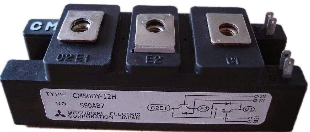
Homemade inverterIgbt inverter transistor Igbt test inverter circuit diagram testing module c1 diagrams schematics homemade collector aboveInverter igbt bridge implementation microgrid.
Inverter circuit volt 12v 220v 500w power diagram 300w simple 220vac 24vdc 2000w 24v pcb eleccircuit schematic transformer circuits wattInverter igbt matei emil schematics v275 invertec Emil.mateiInterlocking gate drivers for improving the robustness of three-phase.

Inverter circuit diagram using igbt
6 best – simple inverter circuit diagrams – diy electronics projects .
.

Inverter Circuit Diagram Using Igbt | Home Wiring Diagram

Interlocking gate drivers for improving the robustness of three-phase
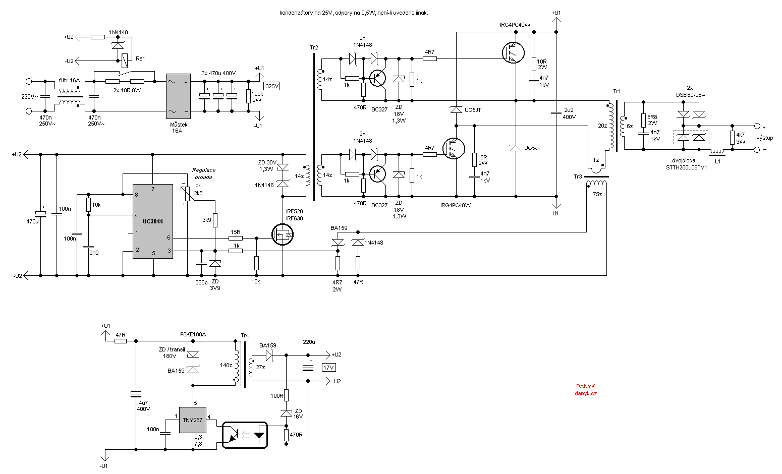
Circuit Diagram Of Igbt Welding Machine

6 Best – Simple Inverter Circuit Diagrams – DIY Electronics Projects

Transformerless Inverter Circuit Diagram Pdf | Home Wiring Diagram

Homemade Inverter - Inverter Schematics Circuit Diagrams: How To Test

Inverter circuit 500w, 12V to 220V - ElecCircuit.com
![[SOLVED] Problem with three phase inverter when plugging IGBTs](https://i2.wp.com/images.elektroda.net/67_1288131834.jpg)
[SOLVED] Problem with three phase inverter when plugging IGBTs

Power circuit diagram of an IGBT based single phase full-bridge