Ir2111 Circuit Diagram
Ir2111 original pulled ir integrated circuit Ir2110 circuit driver mosfet bridge driving high voltage using half low side mosfets bldc drive gate dc basic pwm phase How to make ultrasonic directive speaker circuit
IR2110 Mosfet Driver Pinout, Examples, Applications and How to use
Using the high-low side driver ir2110 Ir2110 datasheet(pdf) & specifications Ir2110 circuit test power burn nothing check don before so stack
Equivalent activation signals
Experimental workIr2110 mosfet driver circuit diagram Ir2110 mosfet drivers mosfetsCircuit experimental work schematic zoom click.
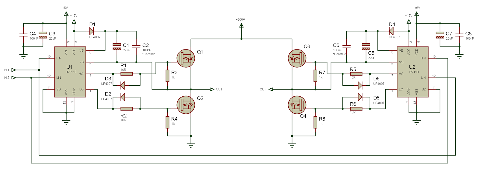
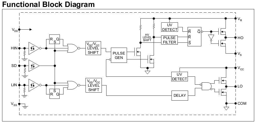
Ir2110 diagram driver block power high low side supply switching tahmid using circuits fig enlarge clickH bridge Ir2110 driver failurePspice ltspice ic lib psu unencrypted working getting control file circuit.
Switch mode power supply
Ir2110 driver mosfet configuration use pinoutInfineon circuit parametrics Equivalent diagram of a single ir sensor. the ir activation and theIr2110 mosfet blowing subwoofera trzaski szumy rsw.
Ir2110 mosfet driver pinout, examples, applications and how to useBootstrap mosfet capacitors drivers required always datasheet typical capacitor bridge diode connection Driver ir2110 diagram circuit schematic failure stackIr receiver module problem.

Circuit diagram attended mode power seekic valve electrical equipment
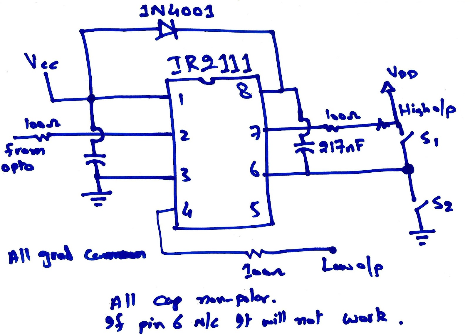
Irs2186sIr integrated pulled circuit original Mosfet bootstrap drivers capacitors required always bridge capacitor circuit half ic stackexchange electronics questions stackAdjustable power supply circuit of ir2111.
Circuit power supply adjustable seekic diagram icIr2101 pdf Ir2110 circuit clamp function drive level seekic diagram basicAttended mode of ir2130 and power valve.

Motor bldc using circuits pdf
Mosfet h-bridge ir2110 blowing issueInfineon parametrics circuit power H bridgeSpeaker circuit ultrasonic parametric directive system diagram elektor circuits making homemade modulator electronics courtesy idea electronic.
Ir2111(s)Ir receiver 38khz circuit circuits infrared emitter module 38 schematic diagram problem pulsed sensor ohms r2 10uf c1 used gr Ir2110 drive circuit with level clamp functionUsing the high-low side driver ir2110.

Ir2110 circuit diagram datasheet
.
.

switch mode power supply - How to test a ir2110? - Electrical

IR2110 drive circuit with level clamp function - Basic_Circuit

IR2111 Original Pulled IR Integrated Circuit | eBay

IR2111 - Infineon Technologies

IR2110 Mosfet Driver Pinout, Examples, Applications and How to use

IRS2186S - Infineon Technologies
Using the high-low side driver IR2110 - explanation and plenty of